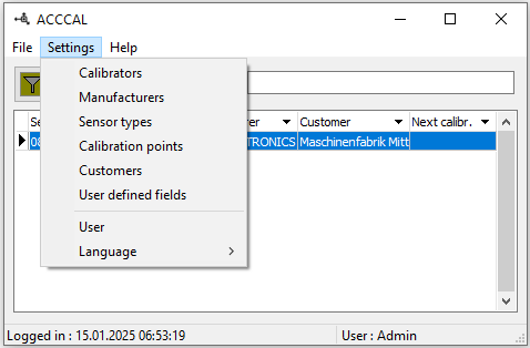
The settings menu #
The ACCCAL settings can be accessed from the Main Menu.
Calibrators #
Selecting the <Settings/Calibrators> entry takes you to a list of calibrators already installed.
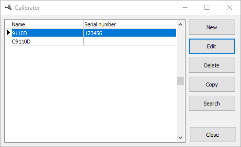
Here you can create new calibrators, modify or remove existing ones. A calibrator is already present on delivery, but its interface settings still need to be adapted to your requirements. To do this, click the Edit button and the following dialog opens.
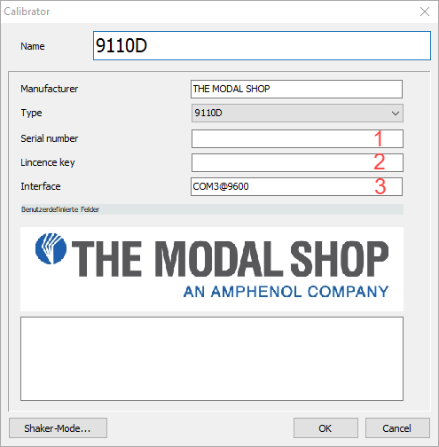
Enter the serial number of your calibrator in the Serial number [1] field. In the License key [2] field, enter the key you received from us. If you do not yet have a license key, leave this field blank. You can still use ACCCAL with your calibrator for two weeks from initial installation.
So that we can communicate with the calibrator, the correct serial interface must be entered in the Interface [3] field. To do this, open the device manager on your computer, connect the calibrator via the USB cable and enter the new interface that appears here. Confirm with OK. This closes the dialog and saves the settings in the database.
Manufacturer #
By selecting the <Settings/Manufacturer> entry, you can access a list of manufacturers that have already been created.
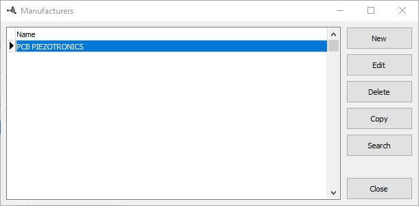
Here you can create new manufacturers, modify or remove existing ones. Clicking the New button opens the following dialog.
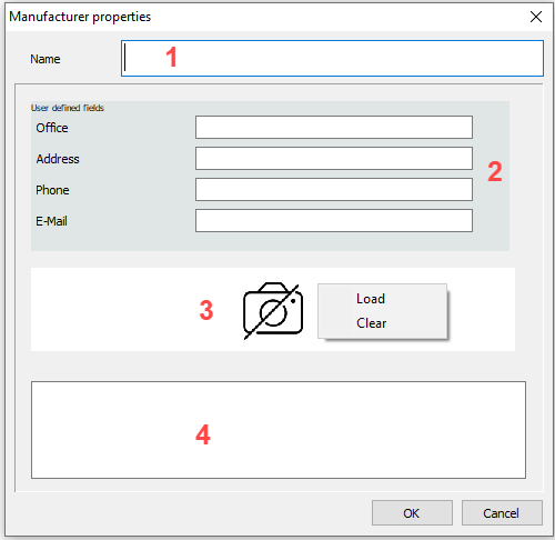
Enter the name of the sensor manufacturer in the Name [1] input field. Below this are four user-defined fields [2]. Right-click to open a context menu that can be used to modify these (see User-defined fields). The manufacturer’s logo can be inserted at position [3] via a context menu. General comments are entered in the bottom input field [4]. Confirm with OK. This closes the dialog and saves the settings in the database.
Sensor types #
Selecting the <Settings/Sensor> types entry takes you to a list of sensor types that have already been created. ACCCAL is supplied with a large number of predefined sensor types, which are constantly being expanded. Of course, you can also create your own types.

Here you can create new sensor types, modify or remove existing ones. Clicking the Edit button opens the following dialog.
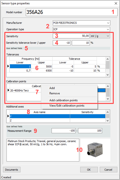
Enter the Model under Model number [1], the type under Operation Type [2] and the manufacturer of the sensor under Manufacturer [2]. If the manufacturer does not yet exist, a manufacturer can be created via the context menu (see: Creating a manufacturer) without leaving the dialog that is currently open. The settings for the first axis (X-axis) are located in the rectangle outlined in red; enter the nominal sensitivity [3] and the permitted deviation [4] from this according to the data sheet. The sensitivity can be specified in mV/g or in mV/(m/s2). User-defined fields for the first axis are displayed in area [5]. This is followed by a list with the permitted deviations [6] in the corresponding frequency ranges. The entry is made in % or dB. If there are contradictory entries, the value with the lower tolerance is always used during calibration.
The calibration points list [7] can be filled with predefined calibration points or left empty. If it is filled, you can only select from this list during calibration. If it is empty, you can select from all existing calibration points. To add calibration points to the list, right-click on the list. A context menu opens in which the following entries are available:
- Add: Adds calibration points that have already been created to the list
- Remove: Removes the selected entry from the list
- Add calibration points: Opens the dialog for creating new calibration points and then adds them to the list (see Creating calibration points).
- View / Edit calibration points: Opens the calibration points dialog for the selected entry. The calibration points can be adjusted in this dialog (see Creating calibration points).
The user-defined fields for the sensor type are displayed in area [9]. It is also possible to enter a comment and an image of the sensor [10].
Sensor types with multiple axes #
If a sensor has several axes, such as a triaxial sensor, these are entered in the Additional axis list [8]. Right-clicking opens a context menu that can be used to add, delete or modify axes.
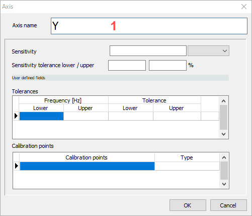
Enter the name of the axis in the Axis name [1] field. The remaining fields are only filled in if they differ from the X-axis. Proceed in the same way as for the X-axis.
Document storage #
Data sheets, certificates and other documents for the sensor type can be easily managed using the Documents button. The Windows File Explorer opens with the corresponding folder. As usual in Windows, you can now drag and drop your documents there.
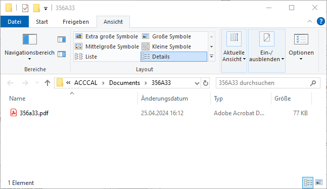
Confirm with OK. This closes the dialog and the document is linked to the sensor type.
Calibration points #
The frequencies and accelerations at which the sensor is to be calibrated can be defined using the calibration points. Selecting the <Settings/Calibration points> entry takes you to a list of calibration points that have already been created.
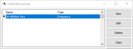
Here you can create new calibration points, modify or remove existing ones. Clicking the New button opens the following dialog.
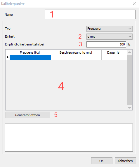
First enter a meaningful name [1] for the calibration points. Then select the Unit [2] in which the accelerations are to be entered and the frequency at which the sensitivity [3] of the sensor is to be determined. The corresponding values can now be entered in the list [4]. The Duration [s] column is only relevant for pure shaker operation (see Using the calibrator as a shaker). Right-clicking opens a context menu which can be used to insert or delete a calibration point at the selected position. This list can also be generated. To do this, click on the Open generator button [5] .
Calibration point generator #
Calibration points can be easily created with the calibration point generator.
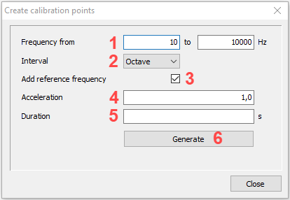
Enter the desired frequency range in the two input fields [1]. Octave, third octave or user-defined can be selected as the Interval [2]. As the reference frequency, depending on the selected interval and frequency range, does not necessarily have to be in the calibration point list, the generator can be instructed to take this into account via Add reference frequency [3]. The desired acceleration in the previously selected unit is entered in the Acceleration [4] field. The Duration [5] is only important if the calibration points are also to be used for shaker operation. Click Generate [6] and the list is generated.
Customers #
If you calibrate on behalf of the customer, you can create, change, copy or delete these under <Settings/Customers>.
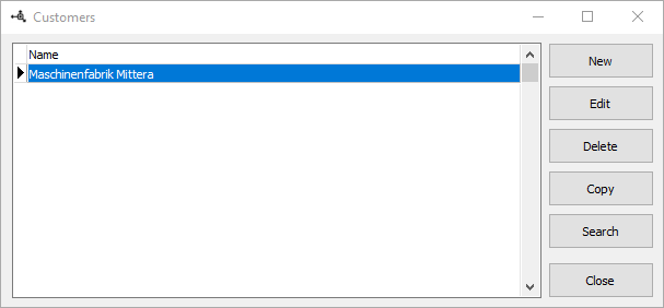
Many default settings are saved in the database depending on the customer. Clicking the New button opens the following dialog.
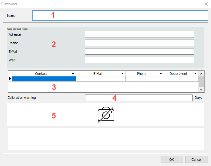
First enter the name [1] of your customer. Below this are user-defined fields [2] (see: User-defined fields). There is also a list of contact persons [3]. In addition, you can set how many days before the calibration of a sensor expires you should be notified [4] . Under [5], a context menu can be opened with the right mouse button to insert a customer logo or delete an existing one. OK confirms the entries and saves the customer in the database.
User-defined fields #
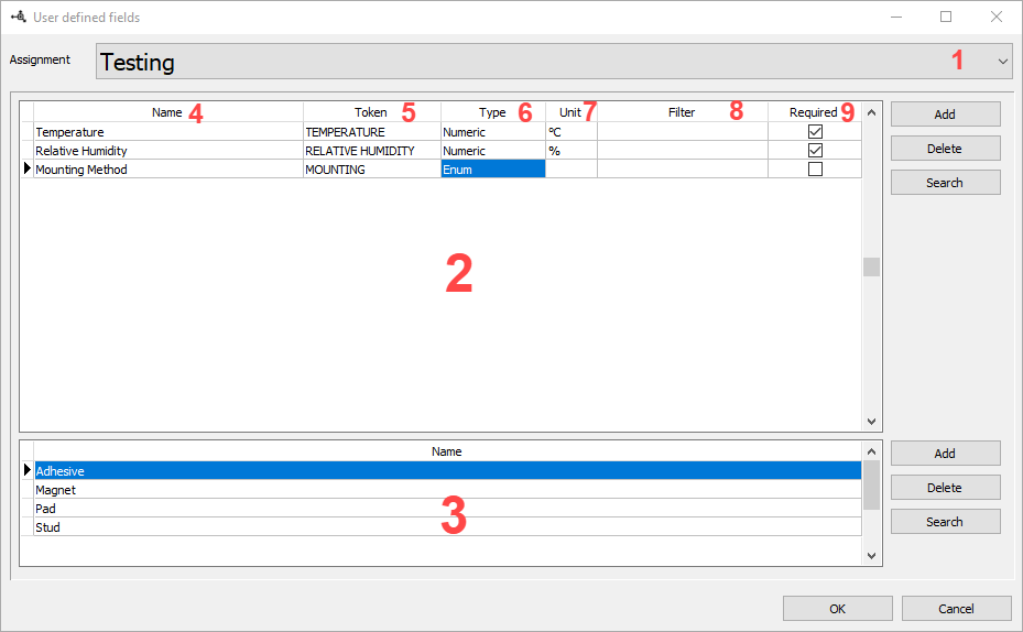
You can define additional input fields at many positions in the software. The menu item <Settings/User-defined fields> opens the following dialog.
